


Modeling & Simulation Environment
This page is a brief description of the Qualitative Dynamical Systems Modeling & Simulation Environment, or QDS MSE. It is arranged as a number of screenshots of the application, which demonstrate its major features, backed by short explanations.
Modes of the Application and Its Screen LayoutsThe Environment is a full-fledged Java desktop application that utilizes McLN Modeling Formalism, described on the page: "Multicolored Logical Net Modeling Formalism", for design, development, and simulation of qualitative dynamical system models. Respectively, the application can be set to operate in either the Development or the Simulation mode. In both modes, the menu item View => Graph or View => Matrix can be selected to represent the McLN models as either the bipartite oriented graph or as the vectors and matrices, constituting the models' vector state space equations. By default, the application is started in Development mode and is set to represent a model being developed in the form of its Graph View. Figure 1 represents the QDS MSE initial screen, presented at the start of the application.
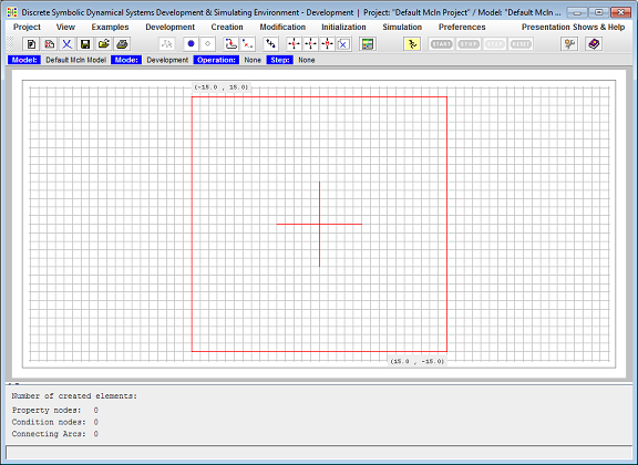
Figure 1. Started Application.
The basic application screen layout includes the following sections (from top to bottom): Menu, Toolbar, Status panel, the Design Space, which can be set in the Model Development or Simulation View mode, the Assisting Tools Area, and the One Line Message panel. The Design Space's Model Development View is the McLN Graph/Matrix View holder. In the usual case, the McLN Graph View occupies the entire Design Space area. However, a developer, in addition to the McLN Graph/Matrix View, may open one of the three optional right side panels: The Initialization Assistant, The Help Topics, or the Preferences Setup panels, as well as one left side panel: Print Preview. The Print Preview panel, when open, takes the left and central parts of the Model Development View area to present its Print Control panel on the left and the Print Page panel in the center of this area.The Development Mode
While in the Development mode, the Environment allows the McLN model developer to create the McLN model Graph, set the model's Properties in their initial state, initialize Arcs with their Expected or Proposed states, save the partially created or complete model on a hard drive, retrieve it, modify it, and save again. The application thus produces an McLN file that is intended to be retrieved by the Space Exploration Mission application into its Robot Behavior Controller (see page: "Space Exploration Mission // An Agent-Robot Behavior Simulator"). Figure 2 represents Design Space's Graph View filled with the Three Rules McLN model and the Initialization Assistant - a wizard-like tool - opened on the right side of the Design Space. Figure 3 represents the same Three Rules model in the Matrix View.
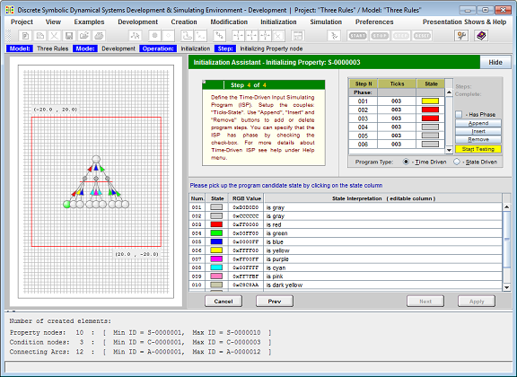
Figure 2. The QDS MSE in the Development mode, presenting a model in the Graph View and the Initialization Assistant on its right side.
The developer switches the Environment to the Development mode by selecting the menu item Development => Set Development Mode. Development mode enables: Creation and Modification menus. Operations available under the Creation menu are to create: Property Nodes, Condition Nodes, Poly-line Arcs, Spline Arcs, and Simple Fragment. Operations available under the Modification menu are to: Move Model Elements, Move Model Fragments, Move Entire Model, and Delete Model Elements.
When in the Development mode, the Assisting Tools Area contains a Summary panel that lists a summary of the model elements by type, providing for each type the number of elements included in the model and the range of their Unique Identifiers - UIDs used so far.
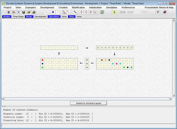
Figure 3. The QDS MSE in the Development mode, presenting the same as in Figure 2, the Three Rules McLN model, in its Matrix View.
Presented in the Matrix View, the McLN model is drawn as five elements - three vectors and two matrices, described below in the order of the data flow in the model:
- The State Vector is the representation of the McLN model's current state.
- The Situations Recognition Matrix is the representation of dependence relations of states of Conditions on the state of Properties. It maps model State Vector to Conditions Vector.
- The Conditions Vector is the representation of the facts of recognition of situations, present in the State Vector.
- The Generation Matrix is the representation of dependence relations of states of Properties on the states of Conditions. It maps Conditions Vector to Final Proposed States Vector.
- The Final Proposed States Vector, which is the representation of the computed next states of the Properties that are supposed to be merged into the State Vector before it is used as the input of the model at the next simulation iteration.
Although both Creation and Modification menus are enabled while the Design Space is set to be in either Graph or Matrix View, all creating new or modifying existing model elements operations can be applied when the model is presented in the Graph View only. The McLN model Matrix View currently serves for visualization purposes only.
The Simulation Mode
While in the Simulate mode, the Environment allows the McLN model developer to test the developed model behavior. When switching to Simulation mode, the Design Space is set to the Model Simulation View, and the Assisting Tools Area, located below the Model Simulation View, is filled with the Property Selection, the Property Current State, and the Execution History Trace Log panels. These currently available tools are assisting in the McLN model development, debugging, and verification. Figure 4 represents a QDS MSE screen snapshot made at the time when the Environment is in the Simulation mode, while the Help Topics panel's Running Model Examples topic is optionally open on the right side of the Model Simulation View.
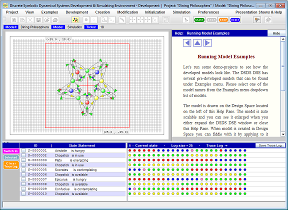
Figure 4. The QDS MSE in the Simulation mode.
The developer sets the Environment to the Simulation mode by selecting the menu item Simulation => Set Simulation Mode. Accordingly, the toolbar buttons enabled in the Simulation mode are: Start, Stop, Step, and Reset. They allow the developer to control the simulation process. Clicking on the Start button activates the auto simulation process. This click disables the Start and Step buttons while enabling the Stop button. Clicking on the Stop button stops the auto simulation process and returns the Start and Step buttons back to their enabled state. Clicking on the Step button executes only one simulation step at a time. Clicking on the Reset button resets the model to its initial state.
The Simulation Analysis Tools, located below the Model Simulation View, allow a developer to select all, or just a subset, of model Properties and analyze the behavior of the model over time in its simulation. The Model Current State Panel presents each selected Property's current state by providing its interpretation in the form of a statement. This interpretation includes the Property name as the statement's subject and the current state of the Property in the form of the statement's predicate. The Execution History Trace Log panel presents selected Properties' state history over simulation time. Both panels are updated after each simulation tick in real time.
Printing Developed Model
The QDS MSE allows the developer to print the developed model. To activate the printing facility, the developer opens the Project menu and selects the Print Preview Panel item, or alternatively clicks the corresponding toolbar button. Figure 5 represents the QDS MSE Design Space at a time when the Environment is set to print a developed McLN model. For the purpose of illustration, this snapshot also presents the Property Setup panel open on the right side of the Design Space panel.
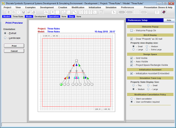
Figure 5. The QDS MSE is set to print the developed McLN model.
As it is presented on the snapshot, the printing facility allows the developer to print in either Portrait or Landscape format. The printed image is scaled to fit the standard A4 page.