


Formalism
This page introduces the Multicolored Logical Net Modeling Formalism, or McLN MF. It is intended for creating graphical models of qualitative dynamical systems and reproducing their behavior on a computer screen. Respectively, in order to enable, not only representing properties of the modeled systems and their states, in the models, but also reproducing changes of the state of the properties, depending on changes of the state of other properties, the McLN models are created based on the notion of the bipartite directed graph, the elements of which are considered to be the simple discrete devices that are endowed with the capability of taking different qualitative states, on the one hand, and having a certain number of inputs and outputs necessary for interaction of the elements with each other, on the other hand.
These models, thus, are defined as the collections of elements representing Properties of the modeled systems, and such elements as the Conditions triggering changes of state of the Properties, Dependencies of the state of the Conditions on the state of the Properties, and the Dependencies of the state of the Properties on the state of the Conditions. Therefore, McLN models are, naturally, created in the form of the graphical nets that are characterized by their structure, and by the mechanism of behavior based on the ability of the elements of the models to perform associated operations of the Algebra of Symbols.
McLN Model Structure and Behavior
Being based on the structure of the bipartite directed graph, the McLN model is constructed of two types of nodes. The Property nodes are depicted as the big circles or big hexagons, states of which are denoted by solid color that fills their surfaces. The Condition nodes are the conditions for changes of states of Property nodes. They are depicted as the small circles that are filled with the solid white color and the sign "+" drawn on it, when the condition is satisfied, or by the plain solid gray color, when it is not satisfied. Two types of Arcs, directed from the Property nodes to the Conditions nodes and from the Conditions nodes to the Property nodes, represent the dependence of these nodes on one another. A simple example of the McLN model is presented in Figure 1.
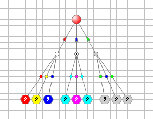
Figure 1. One Property depends on three situations.
Arcs directed from a group of Property nodes to a Condition node represent the dependence of the fact of recognition of the expected situation on a certain combination of states of Property nodes. These arcs are marked with the colored dots, particular colors of which stand for those expected states that the arcs’ input Properties should have in order for their combination to represent the situation that is deemed as the existing and could be recognized.
Arcs directed from a Condition node to a group of Property nodes represent the dependence of the state of the Property nodes on the fact of the existence of the expected situation. These arcs have small arrow heads marked with the colors of the proposed states, which the arcs' output Property nodes should take when the state of the Condition node indicates the fact of recognition of the existing expected situation.
So, the structure of the McLN literally means that the state of each Condition node depends on the state of one or more of its input Property nodes, characterizing a particular expected situation determined by the colors of the dots marking the Properties' output arcs. Whereas, the state of each Property node depends on the state of one or more of its input Condition nodes, and takes state represented by the color of the arrowhead of the arc directed form the Condition node to the dependent Property node in case when the state of the Condition indicates that all its input Properties represent expected situation denoted by the color of the dots of the Condition's input (and the Properties' output) arcs.
Exclusion: Cases when the state of a Condition indicates that the expected situation is not recognized, or the case when two or more Conditions suggest that the Property, dependent on different recognized situations, should take different states, are ignored as contradicting, and the current state of the dependent property stays unchanged.
Example, presented in Figure 1, is created in the "Qualitative Dynamical System Modeling & Simulation Environment" - the software application supporting development of the McLN models and simulation of their behavior.
More on Multicolored Logical Nets, Structure,
Behavior and Simulation Examples
The Front Page is the home page of the stand-alone website, titled “Discrete Symbolic Dynamical Systems & Models”, or “DSDS&M”. It describes the structure and behavior of the McLN models of the qualitative dynamical systems. Open Front Page
The McLN MF page describes qualitative dynamical system modeling technique based on McLN MF, the McLN models structure, and their behavior. It illustrates the description using simple but straightforward examples. Open McLN MF
The McLN Viewer page is the Executor of several pre-created McLN models that can be chosen from the dropdown menu and run by using four control buttons: Start, Stop, One Step, and Reset. Open McLN Viewer